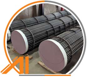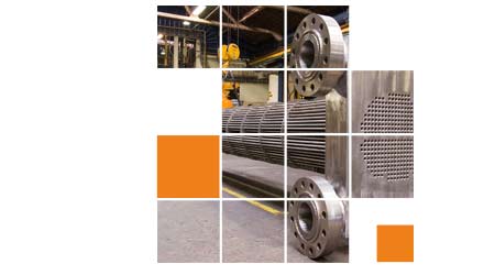
Known as a variant of the tube and shell heat exchanger, the U-Tube heat exchanger is extensively employed in industries like chemicals and petrochemicals for machinery applications. The tube bundle serves as the core component, allowing for unrestricted thermal expansion. It efficiently handles both heat expansion and contraction without exerting pressure on the tubes, making it ideal for scenarios where significant temperature differences exist between the two fluids.
Table of Contents
- U Tube Heat Exchanger Specifications
- Functionality of U Type Heat Exchanger
- Key Features of U Tube Bundle Heat Exchanger
- Design Aspects of U Tube Heat Exchanger
- Diagram of U Tube Type Heat Exchanger
- Comparison: U Tube vs Straight Tube Heat Exchanger
- Distinctive Differences: Floating Head vs U Tube Heat Exchanger
- Applications of U Tube Condenser
- Advantages of U Tube Shell and Tube Heat Exchanger
- Benefits of U Tube Exchanger
- Drawbacks of U-Tube Heat Exchanger
- Calculation Methods for U Tube Heat Exchanger
- Crossover Temperature in U Tube Shell and Tube
U Tube Heat Exchanger Specifications
| U Tube Heat Exchanger Size |
- 0.010 to 1.500 inch OD
- 0.254 to 38.1 mm OD
|
| Manufacturing Type |
- Seamless
- Welded
- ERW
- Fabricated
|
| Major Components |
- Front Header
- Rear Header
- Tube Bundle
- Shell
|
| Standards for Dimensions |
- ASME B16.9
- MSS-SP-43
- ASME B16.28
|
| Manufacturing Process |
- Hot Finished
- Cold Finished
|
| Materials |
- Stainless Steel
- Duplex & Super Duplex Steel
- Carbon Steel
- Alloy Steel
- Nickel Alloy
|
| Certifications |
- MTC EN 10204 3.1/3.2
- 100% Radiography Test Report
- Raw Materials Certificate
- Third Party Inspection Report
- NACE MR0175
- NACE TM-0284
- NACE MR0103
- ISO 15156
|
| Origin |
- Japanese
- Korean
- Indian
- Russian
- Ukraine
- USA
- European
|
| Applications |
- High-temperature
- Low-temperature
- Very high pressure
|
| Surface Treatments |
- Precleaned
- Cleaned
- Passivated
- Pickled
|
| Short Radius Elbow Standards |
|
| Finishes |
- 180 grit polished
- Matt finish
- 320 grit
- Mirror
- Solution annealed
- Annealed & Pickled
- No.4
- 2B
- Cold Drawn
- BA polishing
- 400 grit
- Bright Annealed
- 600 grit
|
| Value Added Services |
- Cutting
- Polishing
- Threading
- Beveling
|
Explore the features and functions of U tube condensers
Functionality of U Type Heat Exchanger
A U-tube heat exchanger facilitates heat transfer between two fluids by channeling one fluid through the tubes and the other around the exterior. It performs exceptionally well in high-temperature and high-pressure applications.
Key Features of U Tube Bundle Heat Exchanger
- Superior heat transfer efficiency
- Fixed at both ends ensuring unidirectional fluid flow
- Easy to maintain
- Simple cleaning process
- Handles high pressures and temperatures effectively
U tube bundle heat exchangers provide efficient heat transfer in a compact design
This design ensures maximum heat transfer capability while reducing energy consumption and operational costs. It exhibits strong pressure tolerance and excellent heat transfer performance, enhancing overall heat transfer efficiency.
Design Aspects of U Tube Heat Exchanger

Examine the components and working principles of U tube shell and tube heat exchanger
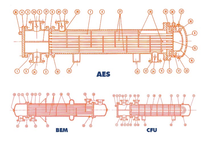
The working principle of U tube shell and tube heat exchanger involves using a shell and tube arrangement to achieve heat transfer. It comprises a shell and multiple tubes. The following figure provides further details about its composition.
Diagram of U Tube Type Heat Exchanger
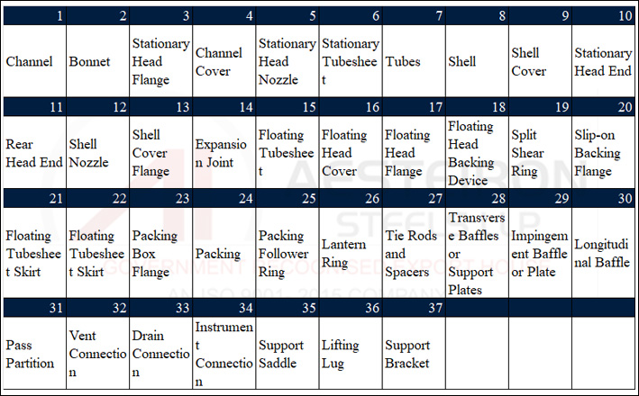
Comparison: U Tube vs Straight Tube Heat Exchanger
| Feature |
U-Tube |
Straight |
| Construction |
Compact and robust |
Simpler |
| Design |
Fixed at both ends |
Bundled in a shell |
| Cost |
High |
Low |
| Thermal Expansion |
More |
Less |
| Heat Transfer Area |
Good |
Better |
| Maintenance |
More complex |
Easier to maintain |
| Space Requirements |
Compact |
Bulkier |
| Lifespan |
Longer |
Varies with design |
Distinctive Differences: Floating Head vs U Tube Heat Exchanger
| Feature |
Floating Head Heat Exchanger |
U-Tube Heat Exchanger |
| Design |
One end is fixed, the other floats or moves |
Fixed at both ends |
| Maintenance |
Easier |
More challenging |
| Heat Transfer Area |
Larger |
Efficient |
| Space Requirements |
Bulkier |
Compact |
| Cost |
High |
Low |
| Lifespan |
Long |
Robust |
U-type heat exchangers are commonly used in petroleum and chemical machinery
As you already know, heat exchangers facilitate smooth heat transfer between two distinct channels, either in direct contact or separated by a barrier to prevent mixing. In the field of petroleum and chemical machinery, U-type heat exchangers are favored due to their compact structure, high heat productivity, and ability to withstand high pressures. These characteristics reduce the risk of heat pressure and failure while enhancing resistance to hazardous conditions.
Applications of U Tube Condenser
- Pressure Vessels
- High Pressure Equipment
- Cryogenic Pressure Vessels
- Boilers
- Air Cooler Tubes
- Tube Sheets of Heat Exchangers
- Refineries
- Air Pre Heater
- Fertilizer Plants
- Chemical Factories
- HVAC Systems
Advantages of U Tube Shell and Tube Heat Exchanger
- High Efficiency
- Enhanced Heat Transfer
- Compact Design
- Minimal Maintenance
- Wide Versatility
- Exceptional Durability
- Cost Effective
- Easy Installation
Review the advantages and disadvantages of U-Tube heat exchangers
Advantages of U Tube Exchanger
- Recyclable
- Energy-efficient
- Various design options
- Cost-effective
- Wide range of materials
- Space-saving designs
- Effective thermal compensation
- Easy maintenance
- Handles diverse flow rates, fluids, and temperatures
Disadvantages of U-Tube Heat Exchanger
- Limited suitability for large temperature variations
- Warping due to temperature differences
- Requires more space
- Needs regular cleaning
- Complex structure
- Prone to internal leaks
U Tube Heat Exchanger Calculation

Crossover Temperature in U Tube Shell and Tube
| Temperature |
Water |
Oil |
| Outlet |
51.5°C |
50°C |
| Inlet |
30°C |
80°C |
| Flow Rate |
15 L/min |
25 L/min |
Concrete Batcher
Concrete batcher machine adopts electronic weighing, which has the characteristics of accurate weighing, high batching accuracy, high speed and strong control function; it is an automatic batching equipment used with Concrete Mixer.
Weighing system:
The measurement method is directly weighed by the sensor, which is accurate and reliable
Storage bin:
Storage bin with a feeding width of 3100mm, which can meet the feeding requirements of 50 loaders;
conveyor belt
The belt conveyor adopts a endless belt to ensure the service life.
Control System
The advanced batching control system is equipped with a special operation remote control handle, which is more convenient to use!
Weigher calibrating
Before leaving the factory, the weights used for electronic scales are verified in the designated scale area to ensure the accuracy of the measurement system.
Structure type
Various structural forms to meet export packing and road freight requirements
Concrete Batcher,Concrete Batching Machine,Concrete Batching Plants,Concrete Batcher With Good Performance
Fangyuan Group Co.,Ltd. , https://www.fygcorp.com


